Protected Mode
What is Protected Mode ?
The 80386+ provides many new features to overcome the deficiencies of 8086 which has almost no support for memory protection, virtual memory, multitasking, or memory above 640K - and still remain compatible with the 8086 family.
The 386 has all the features of the 8086 and 286, with many more enhancements.
As in the earlier processors, there is the real mode.
Like the 286, the 386 can operate in protected mode.
However, the protected mode on 386 is vastly different internally.
Protected mode on the 386 offers the programmer better protection and more memory than on the 286.
The purpose of protected mode is not to protect your program. The purpose is to protect everyone else (including the operating system) from your program.
Protected Mode vs Real Mode
Superficially protected mode and real mode don't seem to be very different.
Both use memeory segmentation, interrupts and device drivers to handle the hardware.
But there are differences which justify the existence of two separate modes.
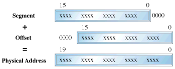
In real mode, we can view memory as 64k segments atleast 16bytes apart. Segmentation is handled through the use of an internal mechanism in conjunction with segment registers. The contents of these segment registers (CS,DS,SS...) form part of the physical address that the CPU places on the addresss bus. The physical address is generated by multiplying the segment register by 16 and then adding a 16 bit offset. It is this 16 bit offset that limits us to 64k segments.
fig 1: Real Mode Addressing
In protected mode, segmentation is defined via a set of tables called descriptor tables.
The segment registers contain pointers into these tables.
There are two types of tables used to define memory segmentation : The Global Descriptor Table and The Local Descriptor Table. The GDT contains the basic descriptors that all applications can access.
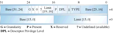
In real mode one segment is 64k big followed by the next in a 16 byte distance. In protected mode we can have a segment as big as 4Gb and we can put it wherever we want. The LDT contains segmentation information specific to a task or program. An OS for instance could set up a GDT with its system descriptors and for each task an LDT with appropriate descriptors. Each descriptor is 8 bytes long. The format is given below (fig 3). Each time a segment register is loaded, the base address is fetched from the appropriate table entry. The contents of the descriptor is stored in a programmer invisible register called shadow registers so that future references to the same segment can use this information instead of referencing the table each time. The physical address is formed by adding the 16 or 32 bit offset to the base address in the shadow register.These differences are made clear in figures 1 and 2.
fig 2: Protected Mode Addressing
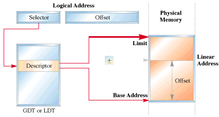
fig 3: Segment Descriptor Format
We have yet another table called the interrupt descriptor table or the IDT.
The IDT contains the interrupt descriptors. These are used to tell the processor where to find the interrupt handlers.
It contains one entry per interrupt, just like in Real Mode, but the format of these entries is totally different.
Entering Protected Mode
The 386 has four 32 bit control registers named CR0, CR1, CR2 and CR3. CR1 is reserved for future processors, and is undefined for the 386. CR0 contains bits that enable and disable paging and protection and bits that control the operation of the floating point coprocessor. CR2 and CR3 are used by the paging mechanism. We are concerned with bit 0 of the CR0 register or the PE bit or the protection enable bit. When PE = 1, the processor is said to be operating in protected mode with the segmentation mechanism we described earlier. If PE = 0, the processor operates in real mode. The 386 also has the segmentation table base registers like GDTR, LDTR and IDTR.These registers address segments that contain the descriptor tables. The GDTR points to the GDT. The 48 bit GDTR defines the base and the limit of the GDT directly with a 32 bit linear address and a 16 bit limit.
Switching to protected mode essentially implies that we set the PE bit. But there are a few other things that we must do. The program must initialise the system segments and control registers. Immediately after setting the PE bit to 1 we have to execute a jump instruction to flush the execution pipeline of any instructions that may have been fetched in the real mode. This jump is typically to the next instruction. The steps to switch to protected mode then reduces to the following:
- Build the GDT
- Enable protected mode by setting the PE bit in CR0
- Jump to clear the prefetch queue
So by doing this you will be in the world of protected mode.

 |
Taj OS
|
Operating System Tutorials
|
Guest Book
|
Sitemap
|
Taj OS
|
Operating System Tutorials
|
Guest Book
|
Sitemap


